


Description
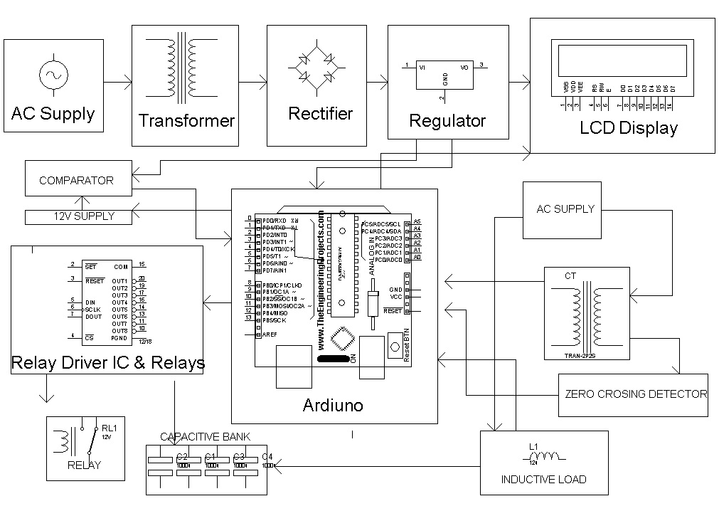
In this proposed system, two zero crossing detectors are used for detecting zero crossing of voltage and current. The project is designed to minimize penalty for industrial units using automatic power factor correction unit.
The time lag between the zero-voltage pulse and zero-current pulse is duly generated by suitable operational amplifier circuits in comparator mode is fed to two interrupt pins of an arduino. The program takes over to actuate appropriate number of relays from its output to bring shunt capacitors into load circuit to get the power factor till it reaches near unity. The capacitor bank and relays are interfaced to the arduino using a relay driver. It displays time lag between the current and voltage on an LCD. Furthermore, the project can be enhanced by using relay control to avoid contact pitting often encountered by switching of capacitors due to high in rush current.
Note = Automatic power factor correction using arduino is the project for the last year engineering project, BE final year project. This project is use for the last year engineering student. It is the project for the arduino base project and zero crossing detector circuit for the detecting for the zero crossing circuit . This project is use for the comparator circuit.
Automatic power factor correction is the project for the last year engineering student for the electrical department use for this project.
This project is use for the electronics engineering student is use for this project.it is use for the power electronics student for the BE final year student.
APFC is the project for the good project, excellent project for the BE last year engineering student. APFC is the project for the competitive project in the BE last year engineering student for electrical, electronics, power electronics student in last year engineering student.
The last year engineering projects, diploma last year, BE last year engineering project give in the project in the ELECTROSAL HI- TECH PVT.LTD. This is the give in the project is best place of the degree and diploma final year engineering projects as well as for electronics student’s and electrical final year student for the golden opportunity.
Automatic power factor correction using arduino it is the project and idea for the electrical, electronics and power electronics last year engineering student
HIGHLIGHTS
- Arduino based project
- The project is designed to minimize penalty for industrial units using automatic power factor correction unit.
- Zero crossing detector concept is used .
BLOCK DIAGRAM
HARDWARE REQUIREMENTS
- arduino
- Op-amps
- LCD
- Shunt Capacitors
- Relays
- Relay driver IC
- Choke
- Crystal
- Switches
- Resistors
- Capacitors
- Diodes
- Transformer
- Lamp
- Voltage Regulator
- Zero crossing detector
SOFTWARE REQUIREMENTS
- arduino
- eagle
- proteus
RESOURCES
I am text block. Click edit button to change this text. Lorem ipsum dolor sit amet, consectetur adipiscing elit. Ut elit tellus, luctus nec ullamcorper mattis, pulvinar dapibus leo.


Abdul Kadir Riyadh(Soudi Arabia) –
Online customer support by the electrosal support team is quite promising. They attended me and solved my doubt each time I made a video call.
Prasad Kulkarni Sangli(Maharashtra) –
i ordered the AUTOMATIC POWER FACTOR CORRECTION USING ARDUINO project. This project is very Nice.
Sudhir Ballolli Hubli(Karnataka) –
I have Order Do it Yourself kit of this project. The project having One ready made kit and another one PCB and their required components. So, i have got a great Experience.
Pratik Gulavani Karwar(Karnataka) –
Had ordered AUTOMATIC POWER FACTOR CORRECTION USING ARDUINO project. the kit was as demonstrated in video n the study material provided with the kit was really helpful, a nice learning experience.
Navoda Supun Los Angeles(United States) –
Nice Customer Support. Thanks For Online Video Call Support.
Kiran Ganeshacharya Thimpu(Bhutan) –
My kit delivery was a day late but no problems since my submissions were late, well I surely learned a lot from this kit it has very detailed explanation documents and videos. Overall a nice experience.
Arpita Mulik Mumbai(Maharashtra) –
Wide range of projects with different Processors and Controllers, choosing just 1 project becomes quite difficult here.
Ramacharan Muthalaly Thiruvananthapuram(Kerala) –
Delivery given to me was upto the mark and in the estimated time. The product was neatly packed with the additional components. excited and already in love with the product.
Manish Kumar Hariyana(Gujarat) –
The projects are demonstrated and made understand in a very simple way. The kit is easy to use.
Siddhu Jadhav Karad(Maharashtra) –
Nice Project.
Bhaskar Abhrange Bengaluru(Karnataka) –
The project quality was very good, I like the way they provide all system development videos along with the kit. I had ordered the AUTOMATIC POWER FACTOR CORRECTION USING ARDUINO kit & am happy to have ordered from here.. no issues at all
Ankit Tiwari Kanpur(Uttar Pradesh) –
This is the most creative automated company I have ever come across.
Sushant Khanal Kathmandu(Nepal) –
Assembling of the electronic system is easy with the help of the demo videos and the cd provided, nice for electronics beginners
Mansi Dixit Poonch(Jammu & Kashmir) –
The online explanation system for my software project kit was wonderful. I saw it 3 times and once again before my final presentation, gave me detailed knowledge of the opinion mining project I bought.
Mandar Bagade West Lafayette(United States) –
Well i got the AUTOMATIC POWER FACTOR CORRECTION USING ARDUINO project and i was surprised to see it delivered in such a good condition. I was afraid that sending a delicate circuit in through international shipping may damage it, but their packaging is extremely good.
indrajeet Mohite Satara(Maharashtra) –
Nice Project. These guys come up with new technology always.
Manoj Bhavikatti Dharwad(Karnataka) –
Good Project.
Omkar Jadhav Pune(Maharashtra) –
My friend told me of these kind of kits available at electrosal.com and i ordered the AUTOMATIC POWER FACTOR CORRECTION USING ARDUINO project. the system is just amazing use of technology. Their tutorials and online support provide sufficient practical knowledge.
Pragati Pachapure Panaji(Goa) –
I have ordered for AUTOMATIC POWER FACTOR CORRECTION USING ARDUINO project. And I have Pay from Google Pay Before 1 day. Very Nice Payment methods and Trustful Company ever i have seen across.
Mahendra Anchan Mangalore(Karnataka) –
i received my kit yesterday, the kit have all the components and parts as mentioned which are pretty exciting. Looking forward to start working on it.
Shrikant Kshirsagar Visakhapatnam(Andhra Pradesh) –
I have Ordered Do it Yourself kit for AUTOMATIC POWER FACTOR CORRECTION USING ARDUINO Project. And Documentation is very Good and in well Format.
Piyush Bhagat New Delhi(India) –
These guys come up with new technology always, keep it up!!!
Vishal Mavdiya –
Project meterial quality is bed
Vishal Mavdiya –
Project material quality is Good
Lalis Yigezu (Ethiopia) –
Calling a Repairman to come into your home can be stressful and overwhelming Mr.Phillips set my mind at ease and fixed my many structural issues he also..
Dadaso Hinge –
Yesterday i received AUTOMATIC POWER FACTOR CORRECTION USING ARDUINO project kit.. kit had all the components and parts as mentioned in component lists. Looking forward to start working on it
Pooja Hegde –
Electrosal company is very nice. Great experience
Poonam More –
Electrical team is very nice
Rakash Desai –
It was good company for learning for learning and ordering your desired project
Ram Patil –
Electrosal was very honest with what needed to be done .